When you’re trying to align a screw to a hole before tightening it, how do you know if the alignment is good? Besides visual confirmation, we can infer misalignment by “feeling” whether the screw is tilted when applying a little downward pressure to it. While this task may be straightforward for a human, it can be quite challenging for an automatic screwdriving machine. Limited by the cost and complexity of integrating high-end sensing solutions, such as computer vision, issues ranging from stripped screws to damaged workpieces persist in conventional assembly industries. In this project, I built a simplified screwdriving station with four strain gauges attached to the supporting beams of a screwdriver, demonstrating rapid and cost-effective sensing of screw alignments.
This was an independent research project I undertook in my third year of university, advised by Dr. Chia-Hung Dylan Tsai, from whom I learned significantly about academic research and conveying ideas. This project not only earned me the required credits for graduation but also made me realize the joy and importance of applying theoretical knowledge from the classroom to solving real-world problems for the first time. To build this screwdriving station and implement the sensing system, I had to recall materials learned from various courses, including mechanical design, manufacturing, electronics, and applied mechanics—subjects that I initially found uninteresting. This hands-on experience allowed me to appreciate the interdisciplinary nature of engineering, where concepts from seemingly unrelated courses converge to solve practical problems.
In the following sections, I will delve into some technical details of the screwdriving station, from the mechanical setup and strain gauge installation to the sensing mechanism and data interpretation. Let’s see how it works!
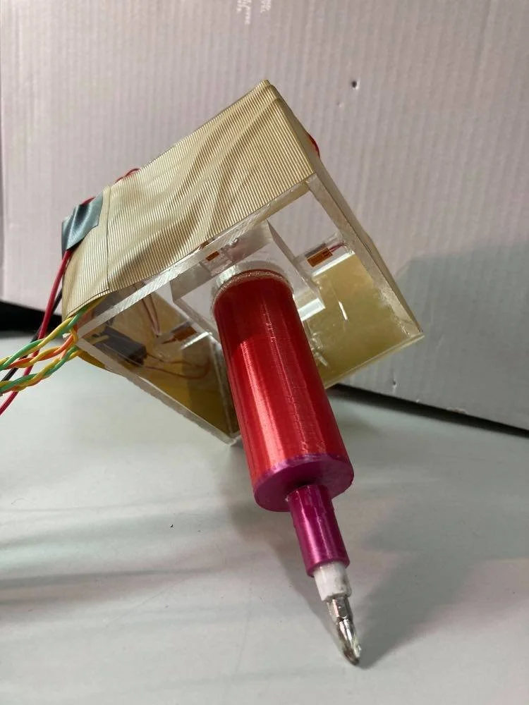
Pictures of the screwdriver and the attached strain gauges.
Screwdriver Design
To sense the orientation of a screwdriver while aligning screw, I’ve spent some time searching for a proper mechanical design that can do the sensing of a moving central part, the screwdriver, subjected to an arbitrary external force depending on the screw alignment. Finally, I found this paper about a F/T sensor design for space manipulator and this paper about motor bracket design for legged robot that resonated well with my task, so I referenced their works and designed the screwdriver with the sensing bracket that consists of four supporting beams attached with strain gauges, as shown in the pictures.
The screwdriver structure (red parts) was made by the FDM 3D printing and a N20 DC gear motor was installed inside. The driver socket was tightly fixed and glued on the head of the screwdriver (which came from my own socket sets). The center bracket, the supporting beams, and the side walls was made by CNC and band-saw cutting of PMMA sheets, and they were assembled using the ARON ALPHA liquid instant glue. The four BF120-3AA strain gauges were bonded on the upper surface of the supporting PMMA beams following the standard bonding procedure with the same instant glue.
Drawing of the screwdriver design.
Static Force Analysis
What will happen when a screw is misaligned, exactly? Through a basic static force analysis on this screwdriver-screw system, we can have some more insights into this daily-life experience in terms of mechanics. I’m not going to bring out all the mathematical formulas here, and I’ll try to discuss the mechanisms in a simplified manner.
The assumptions are:
The screw, the screwdriver, and the PMMA side walls are rigid bodies.
The supporting beams are elastic bodies.
The screwdriver contacts the screw on only one point - the top-center of the screw that sits on its horizontal axis.
Screw orientation when misaligning to a hole.
1. Screw orientation
A misaligned screw means that the horizontal axis of the screw is not overlapped with the central axis of the hole. When pressing the misaligned screw downward, it will be a little bit tilted because the bottom of the screw contacts somewhere at the edge of the hole that deviates from its center. When reaches force equilibrium, the screw would provide a normal force having the same direction as the screw oreintation that acts on the tip of the screwdriver.
2. Beams’ deflection
Here, two major questions need to be addressed: (1) What forces are acting on the beams? and (2) How does each beam deflect under these forces?
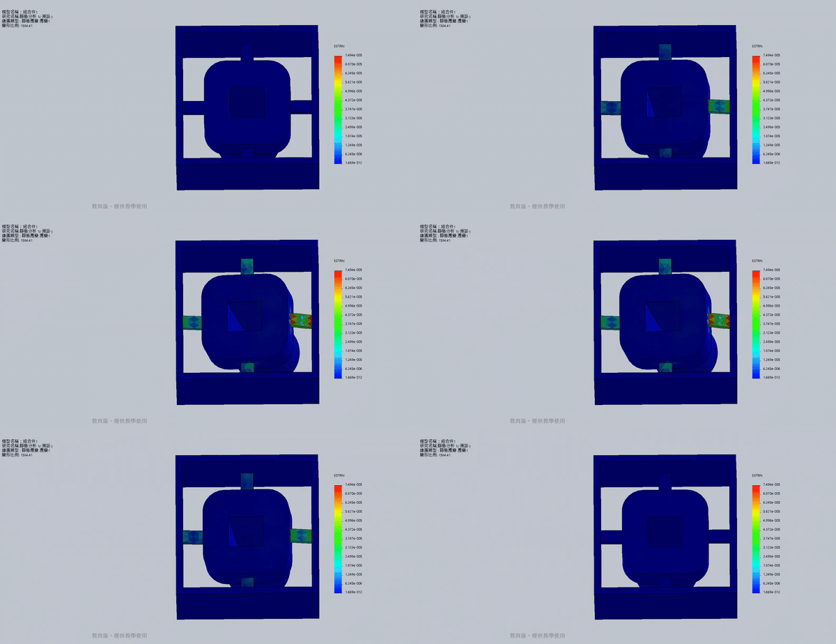
When the screw is perfectly aligned with the hole, the applied normal force is expected to be vertically upward. In this ideal scenario, each elastic beam would experience identical bending upward due to this force. However, when the screw is misaligned, the direction of the applied normal force deviates from the vertical, introducing additional lateral force components. These lateral forces cause the beams to experience not only bending but also compression, stretching, or twisting, depending on the specific direction and magnitude of the misalignment, as shown in the simulation video. Therefore, by measuring the strain on the four beams arranging in a cross-shape, the relative magnitude of lateral forces in X and Y direction could be determined.
A strain gauge is basically a resistor that changes its resistance when deformed, so we can use it to measure the strain on an elastic object. I used Solidworks Simulation to simulate the beams’ deflections when applied a lateral force on the bottom of the screwdriver. While the quantified results were not applicable since I neither estimated the stress on the beams nor used the correct material settings in the frist place, the visualized result showed that they undergoes significant deflections accordingly so I guessed it’s a feasible approach. Next time I’ll do more!
Analysis on the beams’ deflection subjected to an arbitrary point force acting on the bottom of the screwdriver.
Simulation of deflections on the beams (top view) by Solidworks.
Electronics
To detect the small resistance changes in the four strain gauges (typically under 0.1 ohm), I implemented four sets of Wheatstone bridge circuits, each with an instrumentation amplifier on a breadboard. The amplifiers used LM324 operational amplifiers (OPAMP) powered by an 18V supply (two 9V batteries in series), with the gain set to 100. The voltages at the two nodes of the Wheatstone bridge were fed into the instrumentation amplifier separately, where the differential signal was amplified 100 times.
An Arduino Mega 2560 handled data acquisition, calculations, and control signals for motor on/off activation via a relay. When the screwdriver was pressed down manually, the system performed one of two actions based on screw alignment:
If properly aligned, which means the strain gauges’ resistance change evenly, the motor was activated to tighten the screw.
If misaligned, the system claculated and displayed the direction of the lateral force based on the difference of the strain gauges’ resistance variations.
Additionally, I added a calibration button that sends a signal to the Arduino to manually zero the four output signals. This was because the resistance of strain gauges can drift over time, causing the amplifier output to deviate even when the device is idle. To address this issue, I think it would be helpful to replace the standard metal oxide film (MOF) resistors in each Wheatstone bridge with identical strain gauges. This might help normalize resistance variations caused by temperature changes or other external conditions.
Picture of the electronics system setup.
Schematic diagram of one set of the sensing circuit.
Performance testing
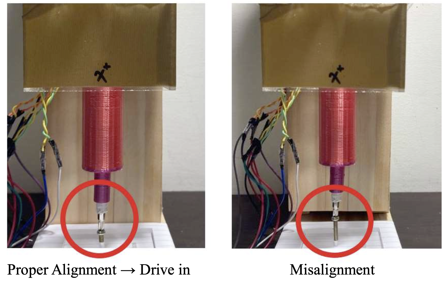
At first, I tested the sensing of screw alignments by simply holding the squared bracket on the top of the screwdriver with my hand and tried pressing the screw downward as vertically as possible. The signal was unstable because my hand couldn’t provide enough stability to fix the side walls when the screwdriver was tilted, but some successful sensing results could still be obtained about 50% across the experiments. Then I decided to make a stable testing platform that can restrict the device’s movement vertically with the side walls being fixed. As shown in the pictures, the final testing platform was made by wooden blocks and the device was fixed on a slider. The slider had to be moved manually as well. I refered to this youtube video about a DIY drill press machine and simplified the design of the supporting structure.
Results
When pressing on a misaligned screw, the signals from the four strain gauges showed significant differences compared to those during proper alignment, as illustrated in the plots. To test the accuracy of the misalignment sensing, I manually adjusted the screw to 8 different misalignment directions relative to the hole, ranging from 0 to 315 degrees using a protractor. The distance between the center of the screw bottom and the center of the hole was set to approximately 1.5 mm. The root-mean-square error (RMSE) in determining the misalignment directions was 25.4 degrees across 24 tests (3 repeated tests for each direction). Additionally, I conducted 16 random trials where the screw was either properly aligned or misaligned (8 trials each). The success rate in determining the correct action (tightening or not) was 87.5%. The results are promising, and I believe the accuracy could be further improved by employing more precise methods for alignment adjustments, such as using XY stages for controlled positioning of the screw or integrating a vision system for validation.
Screw alignment sensing test setup.
Results of the strain gauges’ raw signal for a proper screw alignment (left) and misalignment (right) .
Conclusions & Thoughts
Inspired by a life experience of feeling the screw’s misalignments with hand, I successfully demonstrated the strain-based sensing of screw misalignments with a DIY screwdriving station and the ground-up sensing circuits. The testing result shows that this device can accurately sense whether the screw is in a proper alignment or not, as well as outputting the misalignment directions as the feedback signal for following adjustments. This project was like a comprehensive collection of almost every major subjects that I’ve learned in the university. I used the engineering drawing (via Solidworks) for the device’s deisgn, the mechanical processing skills for fabrications, the force analyses for the theoretical frameworks, the electrionic concepts for implementing the sensing cricuits, and the experimental design for the performance testing. It was exciting to actually use the learned knowledge to solve real-world engineering problems.
I signed up for the 2021 TSPE Research Project and Paper Competition with this work, wrote a formal paper for it, and entered the Final as a poster presentation. Although I didn’t win any prizes in this competition eventually, this experience really opened my mind as I strongly felt the beauty of doing and sharing research. I remember that after the winner announcements, a student came to my poster while I just thinking about packing, so I introduced my work to him as a final mission. After, he told me that my work was very professional and really stood out to the other posters. I believe that this affirmation to my work was the most valuable input along this journey. I’m glad that I determined to put my full efforts into this project!
Me entering 2021 TSPE Research Project and Paper Competition Finals with this work.


