Syringe pump for microfluidic experiments
2024.03
@ IMLab, NYCU DME
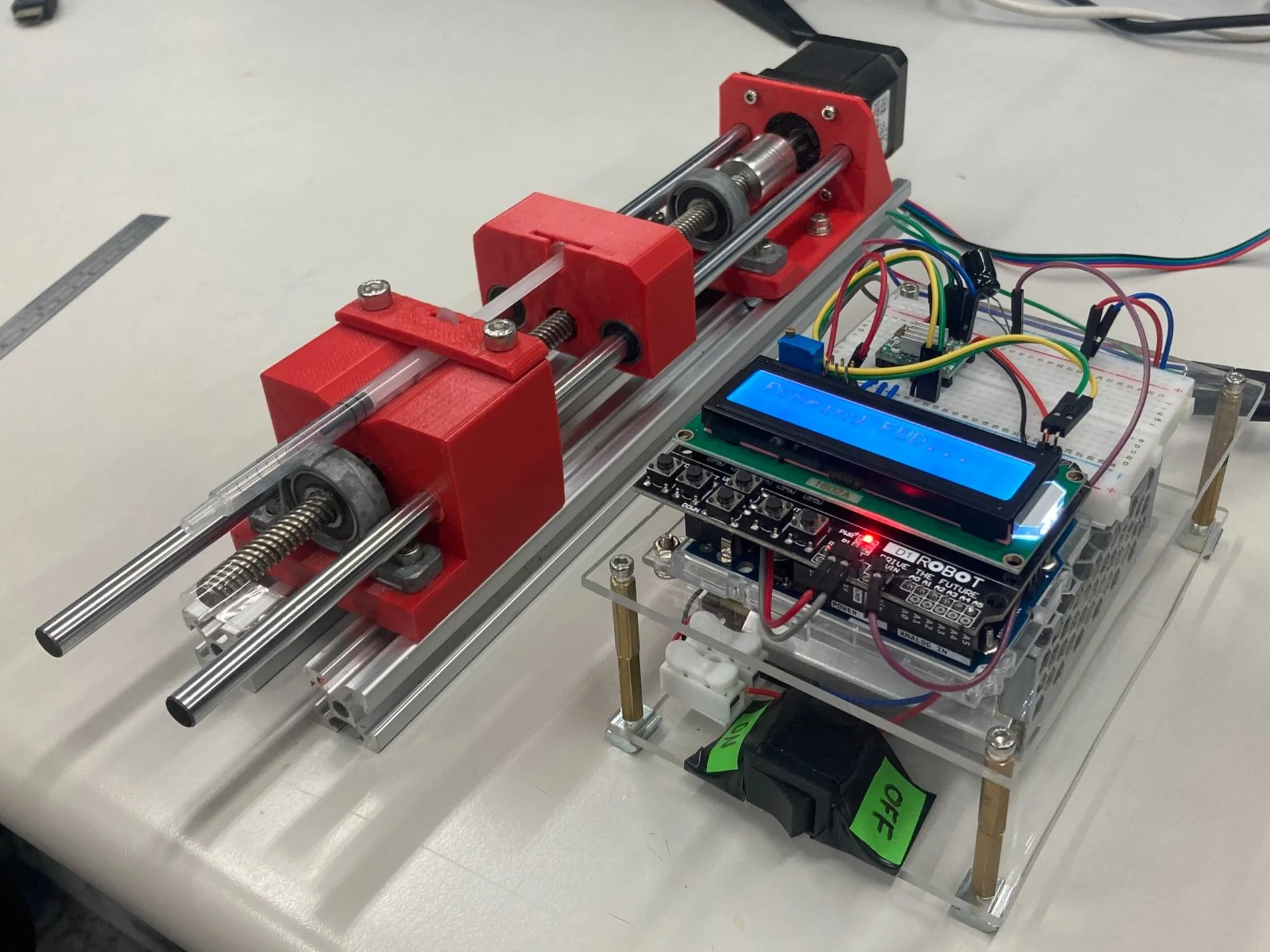
Known for its simplicity and versatility, syringe pumps are widely used in both experimental and clinical applications to autonomously pump fluid samples from a syringe. The basic structure of a syringe pump is straightforward—consisting of a motor, a lead screw, and guiding rods. The rotational motion of the motor is transferred into linear motion by the guiding nut, which pushes the syringe’s piston at a controlled speed. In this project, I built a simple syringe pump that features programmable flow rate settings, direct user interaction, and both infusion and suction options.
This project began during my master’s study in microfluidics when I needed a device capable of dynamically changing the input flow rate. Unfortunately, the syringe pump in our lab could only provide fixed flow rates and lacked suction functionality. I believed these features could be easily implemented with simple motor control, and since the mechanical structure was relatively simple, I decided to build one from scratch. The result was both satisfying and highly functional. Let’s take a closer look!
Mechanical Design
The design was inspired by this published work from a research group in Moscow State University. I referred to this work for the selection of actuating components, including the stepper motor, coupling, linear bearings, guiding rods, and lead screw. To enhance rotational precision and robustness, I incorporated two rotational bearings on the shaft. Luckily, my lab already had all these parts available. The stationary components, such as the motor support, pusher, end support, and syringe clamper (shown in red in the pictures), were designed in SolidWorks and 3D-printed using a da vinci mini w+ printer from our lab. For improved overall stability, I used two aluminum extrusions (25 mm × 25 mm, 350 mm length) as the base structure.
Lead screw mechanism
The key functions of a syringe pump—namely pumping and suction at programmed speeds and volumes—are achieved using a lead screw. The lead screw is a powerful, durable, yet simple mechanism for converting rotational motion into linear motion. At its simplest, a lead screw consists of a threaded shaft and a nut. When the shaft rotates relative to the stationary nut, the nut moves along the shaft’s axis. This occurs because the threads of the screw and the nut act like two interlocking wedges, where one pushes the other in a direction normal to the thread surface when a transverse force is applied. By integrating a stepper motor, which divides motor rotation into tiny, precise steps, the lead screw allows for highly accurate linear positioning, even under heavy loads. To ensure stability and restrict unwanted rotation of the nut, guiding rods with linear bearings are commonly used in such systems. This same approach was applied to my design.
Animation of the parts assembly.
Syringe holders design
If you’ve ever used a syringe to pump a specific volume of fluid, you’ll likely start by holding the syringe with three fingers: the index and middle fingers clamping the syringe’s body for stability, and the thumb placed on the end of the syringe’s rod to apply the pushing force. This concept was adapted into my syringe pump design, where I added grooves to the 3D-printed parts to securely hold the syringe in place. For securing the syringe body, grooves were added to the end support and clamper to accommodate the convex caps on the syringe body. For the pushing and pulling motion of the syringe rod, a groove was added to the front area of the pusher to hold the convex cap at the end of the syringe rod. These features ensure that both pushing and pulling motions are possible, as the syringe is fully fixed in place.
In many commercially available “infusion-only” syringe pump models, the syringe holders typically consist of flat surfaces, as the convex caps on the syringe body are sufficient to limit forward motion. While this design might prioritize compatibility with different syringe types or ease of manufacturing, I believe it sacrifices functionality and operational stability due to the weaker fixture. This limitation was one of my main motivations for this project. I remember thinking, “What’s so difficult about reversing the motor and adding a few tiny grooves to improve the design?”
Grooves design for holding the syringe.
Electronics & Control
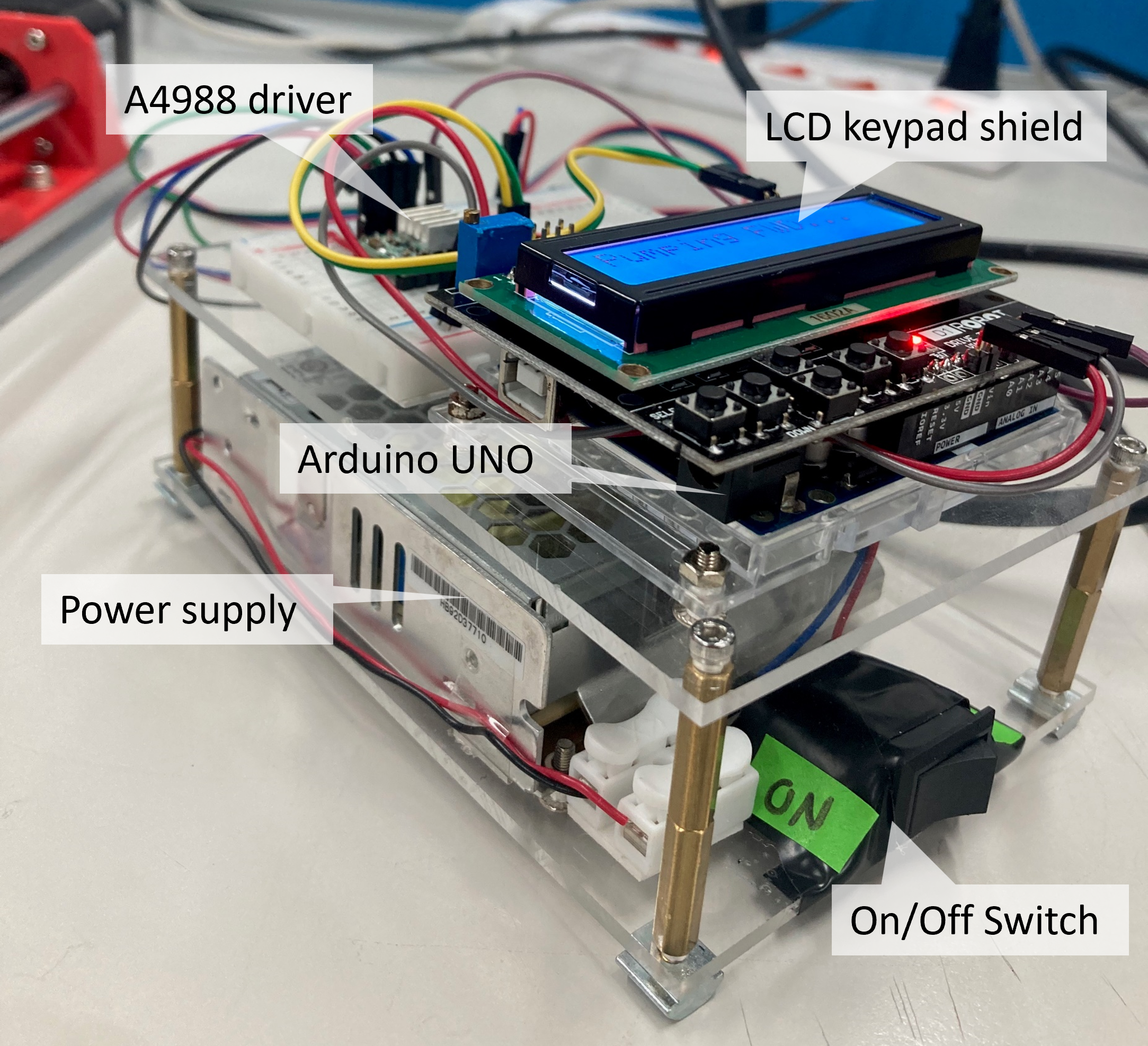
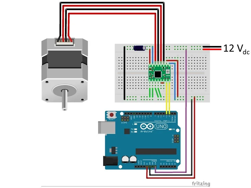
I used an A4988 driver module to control a NEMA 17 stepper motor, powered by a 12V DC, 1.5A power supply. An Arduino UNO served as the controller, sending on/off digital signals to the A4988 driver via two pins to initiate and stop the motor’s steps. This simple electronics setup is commonly found in projects involving stepper motor control, such as 3D printers, robotic arms, and DIY CNC machines.
To achieve the desired pumping speed, the motor step frequency was calculated based on input parameters using a custom program on the Arduino UNO. I enabled all the microstepping pins on the A4988 driver to achieve the highest angular resolution of 3200 steps per revolution, ensuring the smoothest and most precise operation. For user interaction, I integrated an LCD keypad shield with the Arduino, allowing users to set parameters directly without needing a computer. All the electronic components were assembled on a compact, two-layered base to create an organized and user-friendly control panel.
Electronics setup diagram for controlling the stepper motor. Made by Fritzing.
Calculating the frequency of the motor’s steps
Flow rate is defined as the volume of fluid dispensed per unit of time. If we know the volume dispensed by the syringe for each step of the motor, we can easily calculate how frequently the motor should step—i.e., the stepper motor's frequency—to achieve the desired flow rate. To do this, the following parameters are required:
Input Flow Rate: The target flow rate, typically measured in units such as microliters per minute (µL/min).
Syringe Diameter: The inner diameter of the syringe (mm).
Lead Screw Pitch: The linear distance moved by the lead screw in one full rotation, expressed in millimeters per revolution (mm/rev).
Stepper Motor Step Angle: The rotational angle of the motor per step, usually given in degrees (e.g., 1.8°).
Microstepping Setting: The number of microsteps per full step, as determined by the motor driver (e.g., 16 microsteps per step).
First, calculate the cross-sectional area of the syringe based on its diameter. This gives the area in square millimeters (mm²). Next, determine the linear displacement of the syringe pusher per microstep by multiplying the lead screw pitch by the step angle, then dividing the result by 360 and the microstep setting. Using this displacement, calculate the volume dispensed per microstep by multiplying the syringe’s cross-sectional area by the linear displacement per microstep.
To convert the input flow rate to a compatible unit, multiply the flow rate in microliters per minute by 1000, then divide by 60 to get the flow rate in cubic millimeters per second (mm³/s). Finally, calculate the required stepper motor frequency by dividing the flow rate by the volume dispensed per microstep. The on/off period for motor control can then be determined by taking the inverse of this frequency and sending the appropriate signal to the A4988 driver.
Testing
To evaluate the performance of the syringe pump, I first programmed the motor to rotate one full revolution forward and backward consecutively at its maximum speed. The positioning of the pusher was accurate, achieving a displacement of 8 mm per revolution. However, during this initial test, I noticed that the stepper motor became excessively hot after approximately 30 seconds of operation. To address this, I replaced it with a larger NEMA 17 stepper motor capable of handling a higher current input and delivering greater output power. Thanks to the standardized dimensions of NEMA 17 motors, I was able to replace the motor seamlessly without modifying the design of my 3D-printed parts.
For performance testing under actual working conditions, a junior lab member assisted me in comparing the actual pushing distance with the theoretical value over a fixed time interval. Using a syringe with a diameter of 14.56 mm, the flow rate was set to 10 mL/hr, and the pump was operated for 600 seconds. According to the calculations, this setup should result in a pusher displacement of 10 mm. After five repetitions, the average positioning error was reported to be within ±0.05 mm, confirming the accuracy and reliability of the syringe pump.
A simple foward/backward test of the syringe pump.
Conclusion
In this project, I successfully created a syringe pump capable of accurate infusion and suction operations, specifically designed for microfluidic experiments. The use of standardized mechanical components, such as aluminum extrusions and bearings, minimized the need for 3D-printed parts while ensuring precision, durability, and repeatability. An LCD keypad interface enabled direct user interaction, allowing users to control the pump and set parameters on the Arduino controller without the need for a computer. Accurate linear positioning of the pumping operation was demonstrated under the flow rate conditions suitable for conventional microfluidic experiments.
I believe that this syringe pump can be improved further to enhance usability and flexibility. For example, the limit switches can be added to prevent the pusher from exceeding its working range. The pusher design can also be modified to allow manual unlocking of the thread nut for quick adjustments to accommodate syringes of varying lengths. Depite all these, I think this project was really satisfying to me that I built a compact, reliable device with good performance. This experience has not only motivated me to do more advanced projects but also reinforced my understanding of the practice-oriented essence of engineering.


